Overview
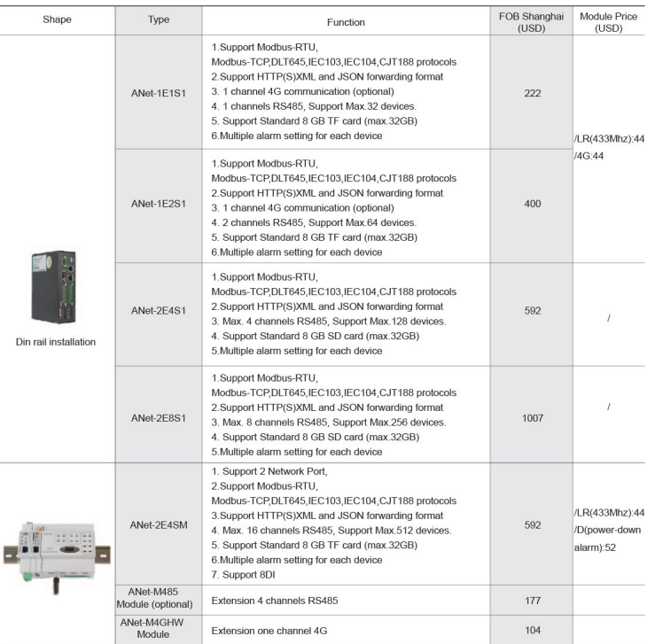
This series of Smart IoT Gateway is an embedded computer hardware platform, with multiple downward communication interfaces and one or more uplink network interfaces, which is used to collect all of the communication data that monitoring or protection devices generated in the target area, then uploads these real-time data to the master station system, thus completing the remote communication, remote sensing and other energy data acquisition functions. At the same time, this series Smart IoT Gateway can receive control commands of the superior master station system and forwarding the commands to an intelligent unit within the target area, such as control the switch on or off, complete device parameters setting, realize remote control and remote adjustable function to achieve the remote scheduling command output goals. This series of Smart IoT Gateway provides a protocol library which contains various kinds of protocols to realize the interconnection of intelligent devices of different secondary suppliers. As the communication interface equipment between the automatic system network and the monitoring equipment, this series of intelligent communication management machine has realized three functions: protocol conversion, interface matching, data conversion. This series of Smart IoT Gateway provides RS485 communication port, each port can carry a maximum of 32 instrument devices (for low voltage integrated protection, it is recommended that each port should be connected with no more than 10); The number of devices carried on each communication port can be finally determined by the communication baud rate, communication line length and customer’s requirement for the refresh rate of communication data. This series of Smart IoT Gateway is capable of real-time parallel multi-task processing, access to third-party devices and communication with host system, and supports software configuration. Through special configuration management software, different communication protocols can be selected for different channel mount devices, and the number of instrument devices connected to the communication manager and data information can be changed by changing the configuration file, without changing the software program.Main Features
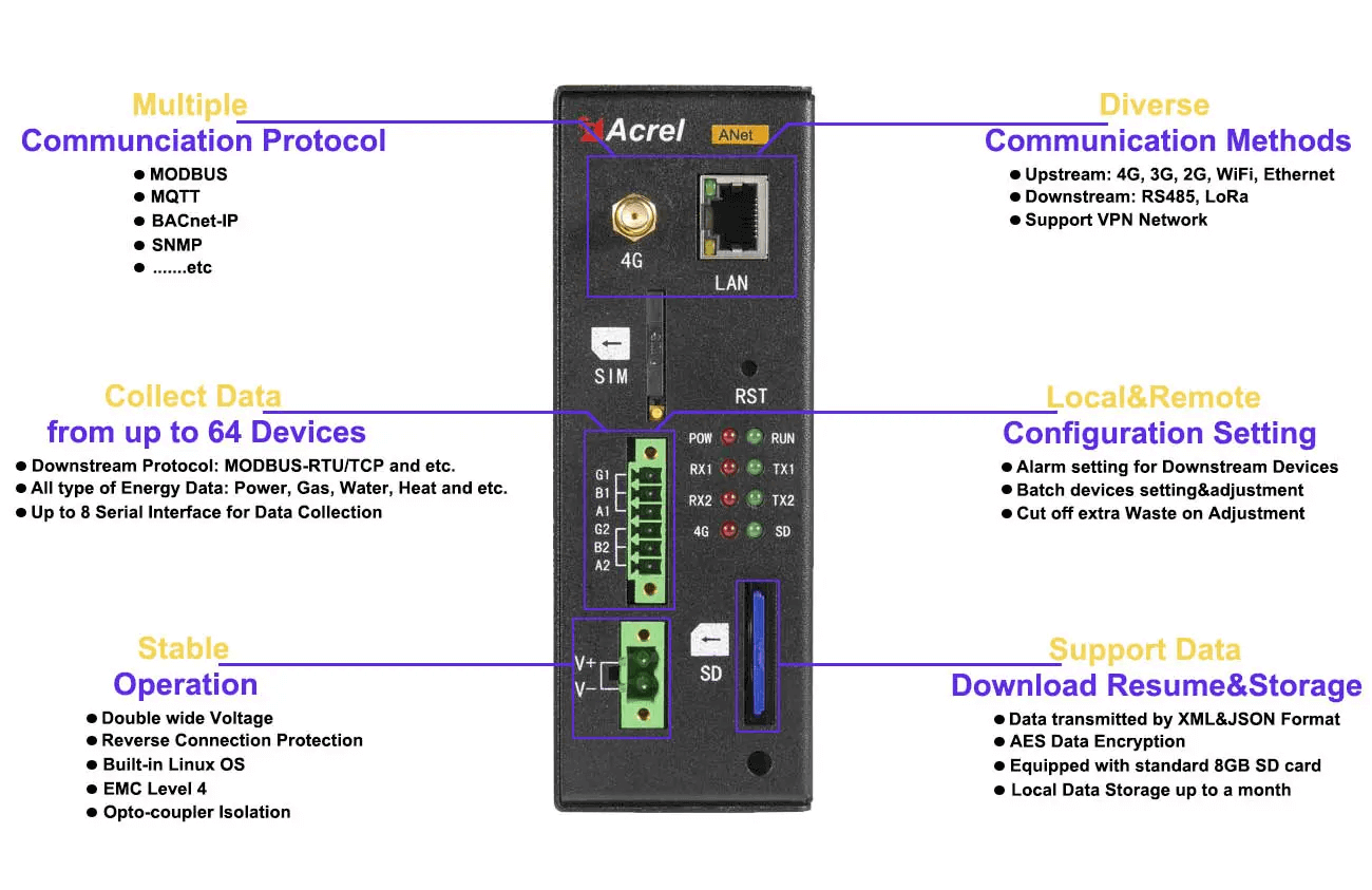
Support Data Download Resume&Storage ● Data transmitted by XML&JSON Format ● AES Data Encryption ● Equipped with standard 8GB SD card (Max. 32GB) ● Local Data Storage for up to a month | 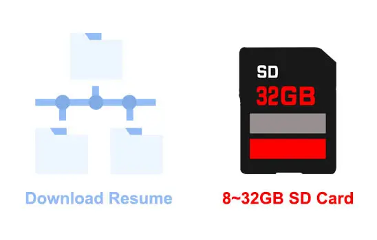 |
Collect Data from up to 64 Devices ● Downstream Protocol: MODBUS-RTU, MODBUS-TCP and etc. ● All type of Energy Data: Electricity, Gas, Water, Oil, Cold, Heat and etc. ● Up to 8 Serial Interface for Data Collection | 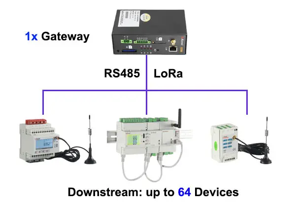 |
Diverse Communication Methods ● Upstream: 4G, 3G, 2G, WiFi, Ethernet ● Downstream: RS485, LoRa ● Support VPN Network | 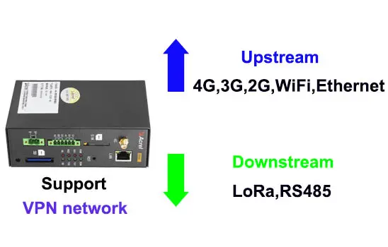 |
Multiple Communication Protocol ● MODBUS ● MQTT ● BACnet-IP ● OPC UA ● WEBService ● SNMP ● …….etc | 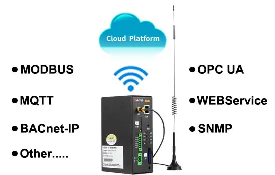 |
Local&Remote Configuration Setting ● Alarm setting for Downstream Devices ● Batch devices setting&adjustment ● Cut off extra Waste on Adjustment | 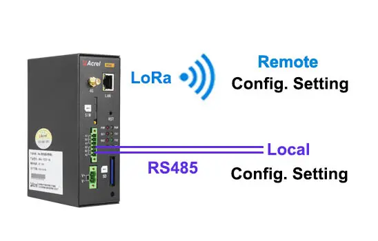 |
Stable Operation ● Double wide Voltage (DC / AC 85V ~ 265V) ● Reverse Connection Protection ● Built-in Linux OS ● EMC Level 4 ● Opto-coupler Isolation | 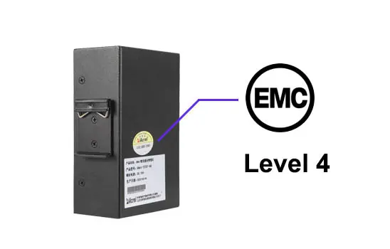 |
Display Sample
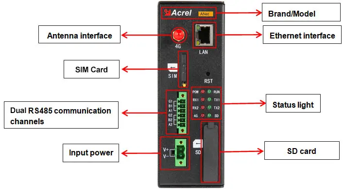
Wiring Instruction
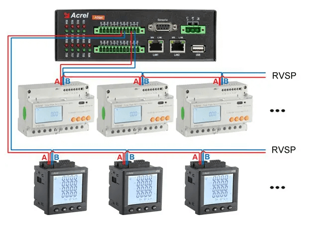
Typical Connection
| Technical Parameter | Indicator | |
| Power frequency &device power consumption | 45~65Hz ,Power consumption≤10W | |
| Security | Electromagne ticcompatibility | ESD L4,EFT L4,SURGE L4,EMI L3 |
| Power frequency withstandvoltage | 1min duration between power supply and communication terminal: 2kV (220V equipment), 1.5kv (24V equipment) | |
| Insulation resistance | In the general test atmosphere, the input and output terminals to device shell >100MΩ | |
| Mean time betweenfailures | ≥30000 h | |
| Environment | Operating temperature:-20℃~+55℃ | |
| Storage and transportation temperature:-25℃~+70℃ | ||
| Relative humidity:≤95%(+25℃) | ||
| Altitude:≤2500m | ||
| External storage | SD card interface 1 channel, built-in 8GB electronic hard disk | |
